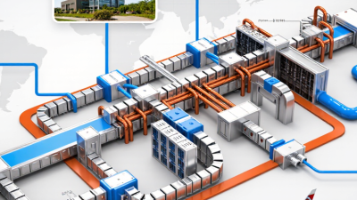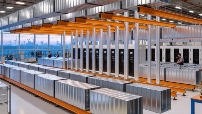
Busways In Electrical systems are becoming more important as factories, hospitals, and data centers demand flexible power distribution. The International Energy Agency’s Electricity 2024 report forecasts data-center electricity use could exceed 1,000 TWh by 2026. That growth puts pressure on capacity, cooling, maintenance, and fault protection. A busway is not simply a metal enclosure with conductors inside. It is a working path through real buildings, above crowded production floors and beside sensitive equipment.
Jim Dollard, an electrical safety specialist associated with NFPA guidance, emphasizes a practical principle: “Safe electrical systems must support the people who operate and maintain them.” That idea should shape every selection decision. A compact busway may save floor space, yet poor access can make inspection awkward. A high short-circuit rating may look reassuring, but coordination studies still matter. IEC 61439-6 also reminds designers that busbar trunking systems require verified construction, temperature performance, and protection characteristics.
This guide examines ten practical tips for choosing Busways In Electrical applications. It considers current capacity, voltage drop, fault withstand, enclosure protection, tap-off units, fire behavior, expansion, installation space, maintenance access, and total lifecycle cost. The weakest point is often overlooked: future change. A system sized only for today may become an expensive obstacle within three years. Specifications also need careful review, because “modular” does not always mean easily adaptable. Real projects are messier than catalog drawings. Therefore, selection should combine manufacturer data, site measurements, qualified engineering review, and honest reflection on how the installation will actually operate.
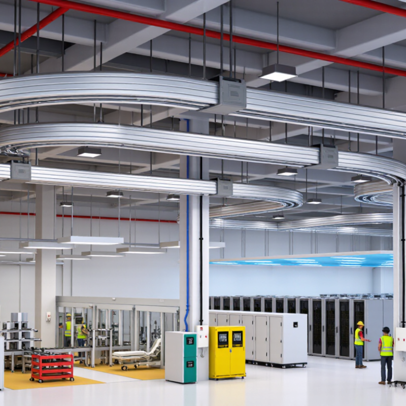
Busway selection starts with understanding the system’s electrical application. Feeder busways carry power from switchboards to distant distribution points. Plug-in busways allow protected tap-off units along production lines or commercial floors. Rising busways connect several building levels through a vertical shaft. They reduce cable congestion, but require careful fire stopping and mechanical support. Non-ventilated designs suit clean indoor areas, while more protected enclosures handle dust, moisture, or accidental contact.
Check the continuous current rating against the real load, not only the planned load. Leave practical capacity for motors, chargers, and future equipment. Confirm voltage, frequency, phase arrangement, and short-circuit withstand ratings with the system engineer. Enclosure protection should match the environment, especially near washdown areas or corrosive vapors. Keep it accessible. Tap-off locations should support maintenance without blocking walkways. Expansion joints may be necessary where buildings move or temperatures change. Poor alignment can create stress at joints and connection points.
During installation, inspect conductor joints, torque values, insulation surfaces, and grounding continuity. A calibrated test meter helps verify resistance and phase identification before energization. Small errors matter. In my field experience, drawings often look complete while access clearances remain unrealistic on site. Rechecking dimensions after other trades install ducts can prevent expensive changes. Thermal scanning during commissioning can reveal loose connections early. Documentation should record test results, joint inspections, protective-device settings, and environmental assumptions. One limitation remains: a technically correct busway may still fail operationally if workers cannot safely reach its tap-off units.
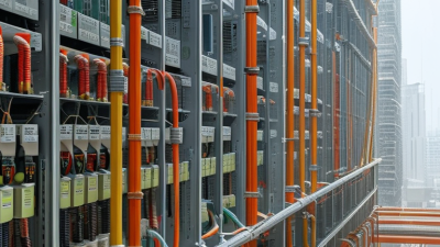
Understanding busway types and their electrical applications helps engineers match current capacity, installation conditions, flexibility, and maintenance requirements to each project.
How to read this chart: The ranges show typical continuous-current ratings commonly available for major busway categories. Actual ratings depend on voltage, enclosure design, ambient temperature, installation method, conductor material, short-circuit withstand requirements, and applicable electrical standards. Always verify the final selection with the manufacturer’s certified technical data.
Busway selection starts with real operating data, not a catalogue rating. The IEA’s Electricity 2024 report estimates data centres used about 460 TWh globally in 2022. It expects demand could exceed 1,000 TWh by 2026. That growth makes accurate load planning essential.
Confirm the system voltage, frequency, phase arrangement, and grounding method. A busway rated for the wrong voltage can create serious insulation and coordination problems.
IEC 61439-6 requires verification of busbar trunking assemblies, including temperature rise and dielectric performance. Those tests matter more than a visually clean installation.
Compatibility includes tap-off units, protective devices, enclosure ratings, and connection spaces. NFPA 70 requires electrical equipment to be installed according to its listing and instructions.
In commissioning reviews, small alignment errors often create hot connections. A neat calculation is not enough. Harmonics, ambient heat, and uneven loading may also reduce practical capacity. I would question any design that uses every available ampere. That assumption is efficient on paper, but fragile in operation.
Selecting materials, enclosures, and environmental protection requires more than comparing ampere ratings. Copper offers strong conductivity and compact joints, while aluminum can reduce weight and material cost. Check conductor plating, joint pressure, temperature rise, and short-circuit withstand ratings under IEC 61439-6 or applicable national standards. Do not guess. A busway sized only for today’s load may restrict future expansion.
The IEA Electricity 2024 report estimates that data centers consumed about 460 TWh globally in 2022, with demand potentially exceeding 1,000 TWh by 2026. Higher density makes thermal performance increasingly important.
Match the enclosure to the site, not the catalog. Indoor dry rooms may suit a basic protection level, but washdown areas, rooftops, and dusty workshops need suitable IP or NEMA protection. Inspect gasket continuity, drain paths, corrosion resistance, and access covers. Salt mist, chlorine, hydrogen sulfide, and ultraviolet exposure can weaken ordinary finishes. Consider ambient temperature, altitude, vibration, seismic movement, and fire separation.
Small details matter. Uptime Institute’s Global Data Center Survey has repeatedly identified power problems among major outage causes, while costly outages remain common. Reliable joints and clear inspection access deserve priority.
A high IP rating is not automatically safer. Poor installation can defeat it. Keep phase spacing, support intervals, expansion joints, and torque records visible to maintenance teams. Review derating calculations with actual harmonics and ventilation conditions.
My own design preference is conservative, but it can add unnecessary cost. Recheck assumptions with measured site data before approval.
10 Tips for Choosing Busways in Electrical Systems
Installation quality begins with the route, not the product sheet. Measure ceiling clearances, access panels, fire barriers, and lifting paths before selecting a busway. IEC 61439-6 emphasizes verified assemblies, temperature-rise performance, and short-circuit withstand. On site, torque records and joint inspections matter as much as ratings. A rushed connection can become a hot connection. I have seen neat installations fail because maintenance access was treated as an afterthought.
Safety requires more than a high fault-current rating. Specify coordinated protection, clear tap-off identification, grounding continuity, and barriers against accidental contact. NFPA 70B now supports documented electrical maintenance programs, including inspection and testing records. The 2024 Uptime Institute outage analysis reported that 53% of respondents considered their latest serious outage preventable. That figure deserves discomfort, not complacency. Thermal scanning, torque verification, and infrared inspection should follow a risk-based schedule.
Expansion changes the decision. The International Energy Agency’s Electricity 2024 report projects data-centre electricity consumption could exceed 1,000 TWh by 2026, more than double 2022 demand. Choose spare capacity, accessible tap-off points, and modular sections before loads increase. Check voltage drop at future demand, not today’s average. Keep drawings current. This is often missed. A busway that supports easy rerouting can reduce shutdown time, but only when floor loading, protection coordination, and ventilation limits are reviewed together. My own preference is to reserve practical capacity, not imaginary capacity; oversized systems can create cost, heat, and space problems.
| No. | Evaluation Area | What to Check | Practical Design Data | Why It Matters | Recommended Action |
|---|---|---|---|---|---|
| 1 | Load and Current Capacity | Assess the connected load, demand factor, motor starting current, harmonics, and expected operating pattern. |
Sizing guide Select a continuous current rating above the calculated design current. A commonly used planning margin is approximately 20–25%, subject to the applicable electrical code and manufacturer test data. |
Adequate capacity reduces overheating risk and limits nuisance tripping during normal or transient loads. | Prepare a load schedule that separates continuous, intermittent, motor, and future loads before selecting the busway rating. |
| 2 | Voltage Drop | Compare the route length, conductor material, current, power factor, and allowable voltage-drop limit. |
Typical target Many designs aim to keep feeder voltage drop near or below 3%, with total feeder-and-branch-circuit drop often planned near 5%. Confirm the project requirement and local code. |
Excessive voltage drop can reduce motor performance, increase heating, and affect sensitive electronic equipment. | Request impedance and voltage-drop data for the selected busway length, joint configuration, and operating temperature. |
| 3 | Installation Route and Layout | Review ceiling height, structural supports, clearances, bends, vertical risers, access points, and obstacles along the route. |
Layout control Coordinate straight sections, elbows, tees, flanges, end feeds, and tap-off locations before delivery. Maintain the clearances required for installation, inspection, and heat dissipation. |
Accurate routing reduces field modifications, alignment problems, installation delays, and unexpected accessory costs. | Create a dimensioned route drawing and verify every connection point against the latest architectural and structural plans. |
| 4 | Protection and Short-Circuit Rating | Confirm the available fault current at the installation point and coordinate the busway with upstream protective devices. |
Safety benchmark The busway short-circuit withstand rating must be equal to or greater than the calculated prospective fault current for the specified duration, such as 0.1 s or the applicable test duration. |
Proper fault-current coordination helps protect conductors, enclosures, equipment, and personnel during abnormal conditions. | Obtain the available fault-current study and verify short-time, peak, and protective-device coordination values. |
| 5 | Environmental Protection | Evaluate moisture, dust, corrosive substances, outdoor exposure, washdown conditions, and the installation location. |
Enclosure selection Use an enclosure rating appropriate to the environment. For example, an indoor dry location may require a basic protected enclosure, while wet or dusty areas may require a higher ingress-protection level such as IP54 or above, subject to the site conditions. |
The correct enclosure helps prevent water ingress, contamination, corrosion, insulation deterioration, and unsafe access to live parts. | Document the environmental classification and specify enclosure, joint-sealing, coating, and corrosion-resistance requirements. |
| 6 | Thermal Performance | Consider ambient temperature, grouping, installation orientation, enclosure ventilation, harmonic current, and continuous loading. |
Temperature check Use the busway assembly's tested temperature-rise limits and apply any required derating. Pay particular attention when ambient temperatures exceed approximately 40°C or when nonlinear loads generate significant triplen harmonics. |
Thermal stress accelerates insulation aging and can reduce service life even when the nominal current rating appears sufficient. | Review temperature-rise test data and calculate derating for the actual installation conditions rather than relying only on nominal amperage. |
| 7 | Grounding and Bonding | Verify the protective-earth path, enclosure bonding, joint continuity, tap-off grounding, and connection to the building grounding system. |
Continuity requirement All exposed conductive parts should remain bonded, and the protective conductor or housing must have sufficient fault-current capability. Final continuity and impedance values must comply with the applicable code and project specification. |
A reliable grounding path helps clear faults quickly and limits touch voltage during insulation failures. | Include bonding details in the single-line diagram and perform continuity, insulation-resistance, and protective-device verification tests before energization. |
| 8 | Maintenance and Accessibility | Assess access to joints, tap-off units, inspection covers, removable sections, and points requiring torque or thermal inspection. |
Maintenance planning Provide safe working clearance and label each section and tap-off point. Inspection intervals should be based on the environment and operating history; thermal scanning is commonly performed during planned energized maintenance where permitted. |
Accessible equipment reduces outage duration and makes it easier to detect loose joints, overheating, contamination, or mechanical damage. | Create a maintenance schedule covering visual inspection, torque verification, cleaning, insulation testing, and thermographic inspection. |
| 9 | Tap-Off Flexibility | Determine how many loads require connection, their operating current, protection type, physical location, and expected changes. |
Distribution flexibility Reserve space for planned tap-off units and verify that each unit is compatible with the busway rating, phase arrangement, protection requirements, and installation orientation. Avoid exceeding the permitted number or spacing of tap-offs. |
A flexible tap-off arrangement allows loads to be added or relocated with less shutdown time and less cable congestion. | Prepare a tap-off schedule showing location, rating, protective device, load type, phase allocation, and spare capacity. |
| 10 | Future Expansion and Documentation | Estimate future load growth, spare capacity, additional floors or production lines, and likely route extensions. |
Expansion reserve A preliminary planning reserve of approximately 15–25% of current capacity is often considered, but the final value should reflect the project forecast, available space, fault level, and economic analysis. |
Early expansion planning prevents premature replacement, major shutdowns, and costly structural changes later. | Maintain current as-built drawings, test records, load schedules, spare-parts information, and clearly identified extension points. |
| Note: All ratings, clearances, temperature limits, protection settings, and installation practices must be verified against the applicable electrical code, project specifications, and tested assembly documentation. | |||||
Choosing busways begins with the load, installation route, and future expansion. Record voltage, current, fault level, ambient temperature, and enclosure conditions. Leave room for growth. Ten percent spare capacity may be insufficient in a changing facility. Compare purchase costs with supports, joints, labor, testing, maintenance, and downtime. Initial price is only one line. A neat drawing can still hide a difficult installation.
Check local electrical codes and project specifications before comparing quotations. Verify short-circuit ratings, temperature-rise tests, ingress protection, fire performance, and conductor materials. Request test reports and certificates for the exact configuration. Generic documents create uncertainty. Standards may differ between regions. Confirm current editions with a qualified engineer and the relevant inspection authority. Do not treat compliance markings as complete proof. Details matter.
Manufacturer support should be measurable. Ask for design reviews, load schedules, layout checks, installation manuals, torque values, and commissioning guidance. Confirm spare joint kits, response times, training, and warranty exclusions. A low quote with weak support can become expensive during a night shift. Compare lead times and local service capability. Ask who answers technical questions after delivery. My checklist is useful, but not perfect. Site access and labor skills can change the result. Recheck assumptions with installers, then document every deviation before energization.