



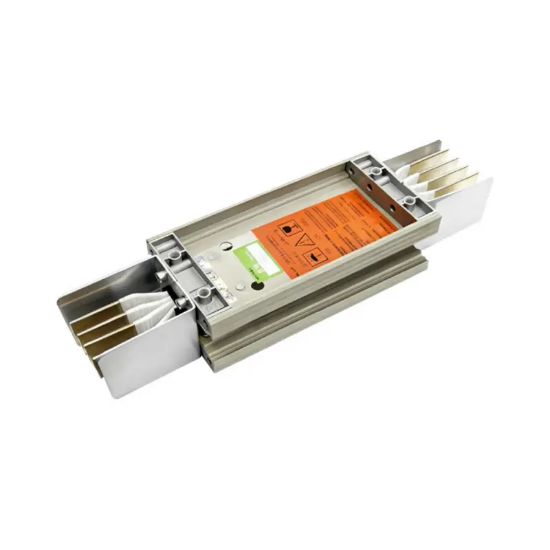
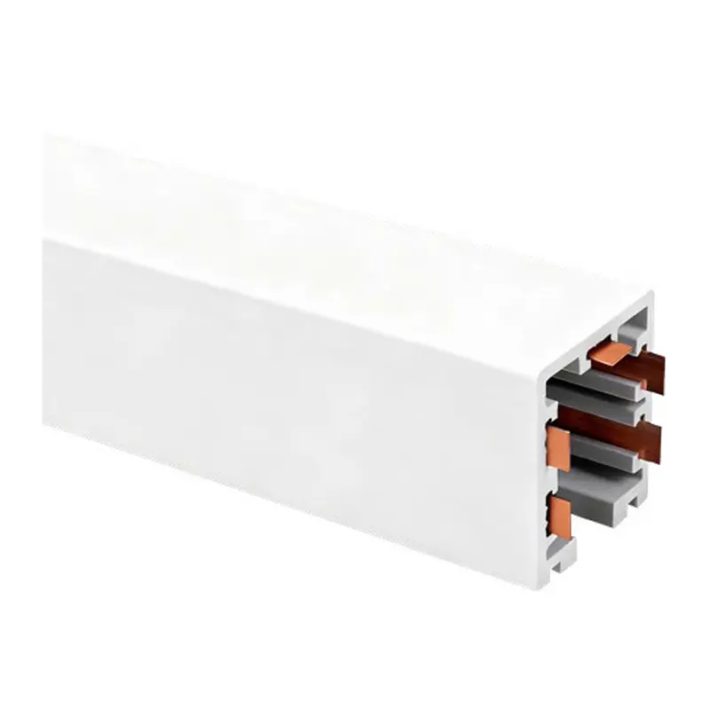


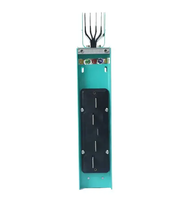
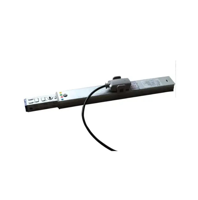
Bus duct connectors generally have the following characteristics during use:
The current bus duct connector will not cause phase misalignment during use, and the installation is relatively quick. Generally, it has the following characteristics:
1 Quick installation
The current bus duct connector cannot be flipped when installed. When two sections of bus duct are connected, the phase will not be misaligned due to flipping.
2 Design double-headed torque bolts
When installing stud bolts, you only need an ordinary wrench to rotate the nut on it until the bolt head breaks automatically and the red indicator gasket falls off, which means the torque has been applied.
3 Pressure equalization
The pressure generated when the bolts are tightened is transmitted to the high-pressure balancing pads of the same cross-section as the copper bars through specially designed washers, so that the pressure on the entire Busway connection surface is balanced. The tightness is moderate, and the electrical connection is safe and reliable.
4 expansion compensation
The joints meet the linear expansion and contraction of the bus duct caused by thermal expansion, and the bus duct connector provides an expansion compensation function of 7 mm, so that the entire bus duct system does not need to install special expansion joint units.
5 High protection level
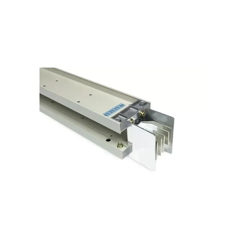
During the installation and use of the bus duct, they are connected in units of sections. The connector is an important functional component for connecting the bus duct. The connector is also called the bus duct connector. Its structure is that the guard plate is fastened with locking bolts. On the insulating guard board, there is a conductive bar between the insulating guard plates. The conductive bar is fixed on the insulating guard board with an injection molding module. The modular fixed pressing plate is between the insulating guard plates. The bus conductor is between the conductive bar and the conductive guard board. Between the rows, both sides of the insulating shielding plates are convex and convex structures. The insulating shielding plates are connected by convex and convex structures. The conductive rows between the two insulating shielding plates are tightly adsorbed on the insulating shielding plates. The insulating shielding plates pass through the copper on the insulating shielding plates. The chip is in close contact with the conductive strip on thE Busbar.