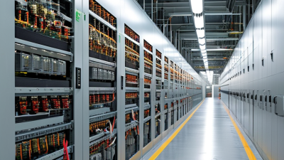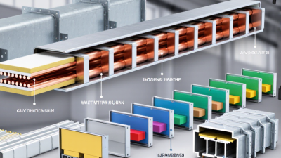
A project’s power distribution system affects far more than how electricity reaches equipment. It shapes installation time, maintenance access, and the space left for future changes. Busduct Electrical systems use enclosed conductors, commonly copper or aluminum, to carry power along defined routes. Their modular sections can run above production lines, through commercial buildings, or between electrical rooms and heavy loads. Tap-off units may provide connection points where equipment needs power. A tidy route can make a crowded ceiling easier to inspect.
That does not make busduct the right choice everywhere. Cable systems may suit short runs, irregular layouts, or projects with limited installation budgets. The decision depends on load requirements, route length, fault levels, ambient conditions, and plans for expansion. Engineers should also check conductor ratings, enclosure protection, support spacing, and the manufacturer’s installation guidance. Small details matter. A poorly planned bend or inaccessible joint can complicate inspection later.
For a fair comparison, project teams can review layout drawings, equipment schedules, and lifecycle costs before selecting a system. They should consider how maintenance staff will isolate and access each section, not just how quickly it can be installed. A busway may simplify upgrades, but only when its route and connection points match actual operating needs. The choice deserves a second look. This article examines the practical reasons teams choose busduct, the trade-offs to assess, and the questions to ask before specifying it.
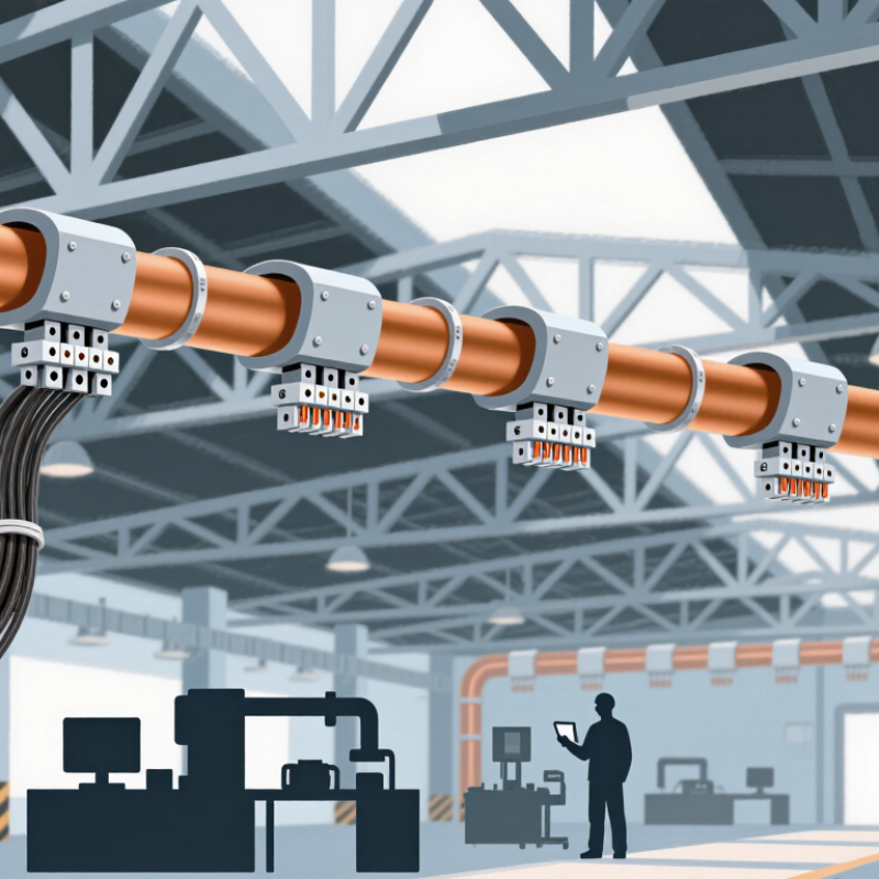
A busduct electrical system is an enclosed assembly of conductors that carries power through a building. It is also called busway. Instead of routing many separate cables, a busduct uses solid copper or aluminum bars inside a protective housing. The enclosure may run above a factory floor, through a commercial building, or between electrical rooms. That matters. It creates a defined route for power and can make connections easier to inspect.
Sections connect along the route, while tap-off units can supply equipment at selected points. A facility might use them to feed production machines or lighting rows. Correct sizing depends on load, voltage, fault levels, temperature, and future expansion. Installation also needs suitable supports, clearances, and grounding. A busduct is not automatically the best choice; tight spaces, unusual layouts, or limited access may favor cable instead. Project conditions can change the answer.
Tips: Check the equipment load and route before selecting a system. Leave room for maintenance and future tap-offs. Ask a qualified electrical professional to verify ratings, joint alignment, and installation details. Small mistakes at connections can cause trouble later.
Typical busduct rated-current levels show how systems can be selected for different project loads.
Busduct, also called busway, is an enclosed assembly of conductors used to distribute electrical power. Its range of available current ratings can support applications from smaller distribution runs to high-capacity systems. Select a rating based on the project’s load, fault level, ambient conditions, and installation requirements; actual ratings vary by system design.
A busduct system moves power from a transformer or switchgear along a building in a protected metal enclosure. Inside, insulated copper or aluminum busbars carry separate electrical phases, with neutral and grounding conductors included as the design requires. Sections connect through joints, forming a continuous route that can run above a factory floor or through a service corridor.
Power reaches individual loads through tap-off units fitted at planned points along the busduct. Each unit connects to a branch circuit and may contain a circuit breaker for protection and isolation. For example, a production line could draw power from several tap-off points without running a separate long feeder back to the main switchboard. The layout still matters. Engineers must check load demand, fault levels, voltage drop, and suitable protection before selecting the system.
On site, details such as joint alignment and secure connections deserve careful attention. After installation, qualified personnel can inspect the assembly and check for unusual heat under operating load. A busduct can make future changes easier, but it is not automatically the right choice for every project. Access, available space, and maintenance routines can complicate a neat design.
Busduct systems can carry power through a building in a compact, enclosed route. Compared with long runs of separate cables, they may reduce cable congestion above ceilings and in service corridors. Less clutter. This can make nearby pipes, lighting, and fire-protection equipment easier to access during maintenance. The rigid sections also provide a clear, predictable path for distribution.
A key advantage is flexibility at the point of use. With suitable plug-in units, power can be tapped at planned locations without routing a new cable run from the main panel. In a workshop, for example, equipment positions may change as production needs evolve. A busduct layout can make those changes simpler, provided the system is designed for the expected loads and connection points. It can also support neat, consistent installation across long routes.
Busduct is not automatically the best fit. Upfront planning matters: engineers need to consider current capacity, fault levels, enclosure rating, thermal conditions, and access for inspection. Poorly placed joints or tap-off points can complicate future work. Cable systems may suit small, irregular spaces better. And a busduct route still needs careful coordination with beams and other services; drawings do not always reveal every site constraint.
| Advantage | What It Means for a Project | Where It Can Be Useful | Planning Consideration |
|---|---|---|---|
| Space-efficient routing | A busduct system can consolidate multiple conductors into a defined enclosure, which may simplify routing in suitable layouts. | Buildings with congested electrical routes, such as commercial buildings and industrial facilities. | Check the full route, including clearances, fittings, supports, and access requirements. |
| Modular installation | Straight sections and purpose-made fittings can create a planned route from compatible system components. | Projects with repeatable layouts or coordinated electrical distribution routes. | Accurate measurements and coordination are important; verify joint locations and installation procedures before work begins. |
| Tap-off connection options | Where the system is designed for it, tap-off units can provide connection points along a busduct run. | Facilities where loads are distributed at multiple locations, such as floors, production areas, or equipment zones. | Confirm permitted tap-off positions, device ratings, protection, and safe isolation requirements for the selected system. |
| Adaptability to layout changes | Some systems allow distribution points to be added or repositioned within the system’s design limits. | Buildings or industrial spaces where equipment locations may change over time. | Changes must remain within the system rating and installation instructions, and may require electrical inspection or approval. |
| Defined system components | Enclosures, joints, elbows, and other fittings are selected as part of a coordinated distribution system. | Projects that benefit from a clearly specified, engineered distribution route. | Use components approved for the exact system and follow applicable electrical codes and installation requirements. |
| Potentially simpler inspection and maintenance access | A visible, organized route can make system identification and access more straightforward when the installation is designed accordingly. | Facilities with planned maintenance programs and accessible service routes. | Provide safe working clearances and follow the required inspection, isolation, and maintenance procedures. |
| Capacity selected for the application | Busduct is available in different current ratings and configurations, allowing engineers to specify a system for the calculated load. | Projects with substantial or centralized power distribution requirements. | Sizing depends on load, ambient conditions, installation method, voltage drop, fault level, and applicable standards; it requires engineering review. |
Suitability depends on the project’s electrical design, installation conditions, local codes, and the ratings and instructions of the selected system.
Busduct systems are commonly used in commercial towers, hospitals, factories, data centers, and large retail buildings. These facilities often distribute power across multiple floors or work areas. In a high-rise, a vertical busduct riser can carry electricity between floors, with tap-off units feeding nearby panels. In a factory, overhead runs can supply production equipment while leaving floor space open. Data centers may use busduct along equipment rows, where power demand can change as servers are added or relocated. The route still matters.
Busduct can also serve airports, campuses, and warehouses with long distances between electrical rooms and loads. Compared with many separate cable runs, a busduct layout can make power distribution easier to inspect and adapt. But it is not automatically the better choice. Heat, dust, moisture, available clearance, load capacity, and access for maintenance all affect system selection. A layout that looks efficient on paper may be awkward to service once ceilings and equipment are in place.
Tips: Confirm load requirements and installation conditions with a qualified electrical professional. Check clearances, joint access, and future expansion space before fixing the route. Small planning oversights can become expensive to correct.
Busduct selection begins with the actual load profile, not just the switchboard’s nameplate rating. List present demand, expected equipment additions, operating hours, and any large motor-starting loads.
Not just capacity. Confirm voltage drop and short-circuit withstand ratings against the installation’s electrical study.
Next, examine the route. Measure ceiling clearances, turns, support points, and access for tap-off units. Ambient temperature, vertical runs, enclosure rating, and nearby heat sources can affect the suitable configuration.
Maintenance matters too: a tap-off point above a crowded service corridor may be technically workable but awkward to reach. A neat drawing can still hide a poor access route. Review installation space with the people who will maintain the system.
Then compare the complete installed cost, including supports, joints, firestopping, and planned shutdown time—not only the price per metre. A little uncertainty remains until site conditions are checked.