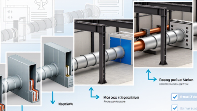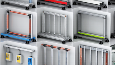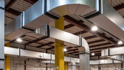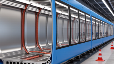
Bus Duct systems carry electrical power through enclosed conductors, often between transformers, switchgear, and distribution panels. Their metal housings protect the conductors and provide a compact alternative to long cable runs in many commercial and industrial buildings. The right design depends on more than current rating. Voltage, fault withstand, installation space, ambient conditions, and future expansion all matter.
This guide explores ten commonly discussed types, including feeder, plug-in, lighting, sandwich, air-insulated, and phase-segregated designs. The names can overlap: some describe construction, while others describe use or conductor arrangement. That distinction is easy to miss. A plug-in system, for example, may suit a factory floor where loads change, while a feeder design may serve a fixed route between major electrical equipment. Real installations also involve practical details, such as joint access, support spacing, heat buildup, and clearance around bends. Small details matter.
No single type is best for every project. A compact unit may save room but leave less space for inspection or later changes. Ratings and installation requirements should be checked against manufacturer documentation and reviewed by qualified electrical professionals. This overview offers a starting point, not a substitute for project-specific engineering. The comparisons are useful, but some categories are not perfectly comparable—and that is worth keeping in mind.
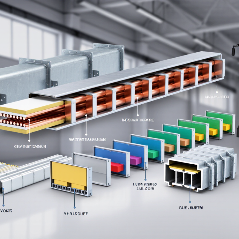
Feeder and plug-in bus ducts serve different jobs. A feeder bus duct carries power from a transformer or switchboard to a downstream panel. A plug-in bus duct adds access points for tap-off boxes, letting teams connect loads along the route. The distinction matters in buildings where equipment may move. It matters even more when circuits are added later.
The IEA’s Electricity 2024 report estimates that data centres used about 460 TWh of electricity worldwide in 2022. It projects demand could reach 620–1,050 TWh by 2026. That is not a bus duct market forecast, but it points to growing pressure on concentrated power systems. Feeder sections can suit fixed, high-capacity routes. Plug-in sections offer more connection flexibility, though every tap-off still needs suitable protection and load planning. No shortcut here.
Design checks should cover current rating, ambient temperature, short-circuit withstand, and installation clearances. IEC 61439-6 addresses busbar trunking systems and provides a relevant framework for verification. On site, inspect joint alignment and access-box seating; a small gap or loose connection can become a serious maintenance concern. A tidy drawing can still hide a poor load assumption. I would recheck expected growth before fixing tap-off locations.

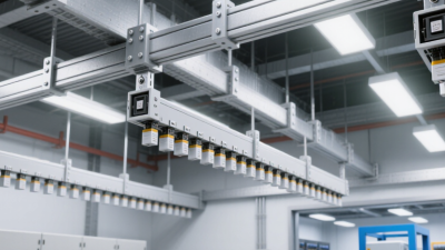
Lighting bus duct distributes power to rows of fixtures through an enclosed conductor system. Instead of running a separate cable to every light, installers can use plug-in outlets along the route. That can make layout changes easier in workshops, retail spaces, and other areas where lighting positions may shift. A practical detail: keep access points clear, so adding or servicing a fixture does not require dismantling nearby equipment. Small planning choices matter.
Trolley bus duct serves moving electrical loads. A traveling trolley or collector draws power from conductors inside the track, supporting equipment such as hoists or other movable machinery. The collector must match the duct system, and the route needs enough clearance for smooth travel. Inspect wear points regularly. Dust, vibration, and frequent movement can affect contact quality over time.
These systems solve different problems. Lighting duct distributes power to fixed fixtures; trolley duct follows equipment along a path. Selection should reflect load, travel distance, installation conditions, and maintenance access. A common mistake is choosing by appearance alone. It looks simple, but the actual operating pattern may expose gaps in the design. Have a qualified electrical professional verify the load and protection requirements before installation.
Air-insulated and sandwich bus ducts are two common types among the many systems used to distribute power in buildings and industrial facilities. In an air-insulated design, conductors sit apart inside an enclosure, with air providing much of the insulation. The visible spacing can make inspection easier. It also means the assembly may need more room.
That gap matters. Air-insulated ducts can suit routes where space is available and access for inspection is useful. However, dust, moisture, and installation clearances deserve attention. A clean-looking enclosure does not guarantee clean insulation. Check the specified environment, enclosure rating, and support spacing before choosing a system.
Sandwich bus ducts place conductors close together, separated by solid insulating material and enclosed in a compact assembly. Their smaller profile can help in crowded risers or plant rooms. Less space, sometimes. But compactness does not automatically mean better performance: heat dissipation, temperature-rise ratings, and short-circuit withstand must match the actual load. A specification should also account for joints, since poor alignment or insufficient tightening can undermine an otherwise suitable installation. It is easy to focus on the straight run and overlook the connection points.
Non-segregated and segregated-phase bus ducts differ in how their phase conductors are separated inside the enclosure. In a non-segregated design, all phases share one housing without grounded barriers between them. Insulating supports hold conductors in place, while specified clearances help manage electrical stress. This arrangement can be compact and straightforward to inspect, but careful installation is essential. Dust, moisture, loose joints, or damaged supports can undermine performance. Small details matter.
A segregated-phase bus duct places grounded barriers between the phase conductors inside a common outer enclosure. These partitions provide physical separation, but they do not eliminate electrical risk or replace correct equipment ratings. The design may suit installations where phase separation is an engineering requirement, though barriers can add weight and inspection points. Engineers should check current capacity, short-circuit withstand, enclosure conditions, support spacing, and joint access against the actual layout. I would not choose by appearance alone; site conditions can change which design fits better. Neither option is foolproof.
What Are the Top 10 Types of Bus Duct?
Isolated-Phase and Weatherproof Bus Ducts
Isolated-phase bus duct keeps each phase conductor inside its own grounded metal enclosure. This arrangement is common in high-current connections between generators and transformers. The metal barriers help limit phase-to-phase faults and reduce magnetic forces during short circuits. IEEE Std 605-2008 provides engineering guidance for bus design, including clearances and thermal considerations. Actual ratings depend on the installation, so a drawing alone cannot replace site-specific checks. That detail is easy to miss.
Weatherproof bus duct needs an enclosure selected for the actual exposure, not just an outdoor label. IEC 60529 classifies IPX4 as protection against splashing water from any direction; IPX5 addresses water jets, a different test. Rain, wind-driven spray, condensation, and salt exposure can each affect enclosure choices and maintenance. Inspect joints, gaskets, and supports after installation, especially where water may collect. Keep drains clear. A rating does not guarantee a leak-free installation if covers are misaligned or seals are damaged. I would verify the specified IP rating against the equipment location and the manufacturer’s test documentation, then revisit it after field changes.
| Type | Basic construction | Common applications | Key selection considerations |
|---|---|---|---|
| 1. Non-segregated-phase bus duct | All phase conductors share a common enclosure without grounded metal barriers separating the phases. | Indoor connections between generators, transformers, and switchgear, where the design and installation conditions allow. | Check short-circuit withstand, clearances, ventilation, insulation system, and the applicable electrical standards. |
| 2. Segregated-phase bus duct | Phase conductors share a common enclosure but are separated from one another by grounded metal barriers. | Power-station and industrial power connections where phase separation is part of the specified design. | Review barrier construction, enclosure grounding, temperature rise, fault ratings, and maintenance access. |
| 3. Isolated-phase bus duct | Each phase conductor is installed in its own separate grounded metal enclosure, with spacing between phase enclosures. | High-current generator connections in power plants, including generator-to-transformer runs. | Consider continuous-current and short-circuit ratings, enclosure bonding, support design, thermal expansion, and installation clearances. |
| 4. Air-insulated bus duct | Conductors are supported within an enclosure with air serving as the main insulating medium between conductors. | Applications where the equipment layout and enclosure size can accommodate the required conductor spacing. | Account for required clearances, ventilation, contamination, condensation, and the manufacturer’s installation limits. |
| 5. Sandwich busway | Insulated conductors are arranged closely together in a compact enclosure, reducing the overall busway profile. | Building distribution and industrial power distribution where space-efficient routing is useful. | Check current and fault ratings, heat dissipation, joint access, mounting orientation, and compatibility of fittings. |
| 6. Feeder busway | A busway section designed primarily to carry power from a source to downstream equipment; it generally has no regular tap-off openings along its length. | Connections between transformers, switchboards, motor control centers, and distribution panels. | Confirm the route, ampacity, voltage drop, short-circuit rating, joint locations, and expansion requirements. |
| 7. Plug-in busway | A busway system with designated tap-off openings that accept compatible plug-in units or tap boxes. | Commercial and industrial facilities needing flexible distribution to equipment or changing loads. | Verify tap-off unit ratings, permitted installation positions, protection coordination, and safe access to outlets. |
| 8. Weatherproof bus duct | An outdoor-suitable bus duct enclosure designed to resist weather exposure when installed and maintained as specified. | Outdoor connections between electrical equipment, or routes exposed to rain and other environmental conditions. | Specify the required enclosure protection for the actual site; consider rain entry, drainage, condensation, corrosion, seals, and temperature range. |
| 9. Indoor bus duct | A bus duct system intended for indoor locations with environmental conditions within its specified limits. | Electrical rooms, factories, and other protected interior spaces. | Check the enclosure rating, ambient temperature, dust or moisture exposure, fire-stopping at penetrations, and access for inspection. |
| 10. Outdoor bus duct | A bus duct system selected for outdoor installation; its enclosure and fittings must suit the expected environmental exposure. | Outdoor substations, plant equipment connections, and exterior distribution routes. | Confirm the required environmental rating, UV and corrosion resistance, drainage, support spacing, and protection against water ingress. |
Note: These categories describe different design or installation features and can overlap. For example, a feeder busway may also be weatherproof or use a sandwich construction. Select equipment according to the project’s electrical ratings, environment, applicable codes, and manufacturer documentation.