Choosing the right Medium Voltage Bus Duct begins with more than comparing prices or catalog dimensions. The decision affects electrical safety, installation time, heat management, and future maintenance. A suitable system must match the project’s voltage, continuous current, short-circuit withstand rating, and connection layout. It should also fit the building’s real conditions, including dust, moisture, altitude, ambient temperature, and available clearance.
Look closely at the details. A bus duct passing through a compact electrical room may need a smaller bending radius and stronger enclosure protection. Outdoor sections may require weather-resistant materials and carefully sealed joints. Ask manufacturers for verified test reports, temperature-rise data, insulation ratings, and routine inspection requirements. Independent certification and compliance with applicable electrical standards matter. So does the supplier’s installation experience. A technically strong product can still perform poorly when joint torque, alignment, or support spacing is overlooked.
There is no universal best choice. Not quite. The lowest initial cost may create higher losses or difficult maintenance later. Conversely, an oversized system can waste space and budget without improving reliability. Engineers should compare lifecycle cost, expansion plans, spare-part access, and shutdown requirements. Project drawings must be reviewed with the manufacturer before fabrication. One overlooked dimension can delay an entire switchgear connection. Site conditions also deserve honest discussion, because assumptions often fail during installation. By combining measured project data, qualified engineering review, and credible manufacturer evidence, buyers can select a Medium Voltage Bus Duct that is safe, practical, and dependable for its intended service. Expect some uncertainty, and document it before approval.
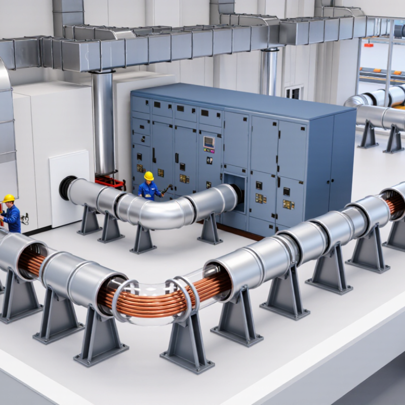
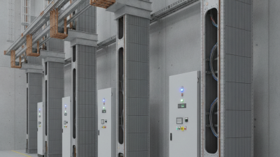
Medium voltage bus duct is a metal-enclosed power distribution system for medium voltage circuits. It contains insulated conductors, protective barriers, and joints inside a rigid enclosure. Depending on regional standards, medium voltage commonly covers systems above 1 kV and up to about 35 kV.
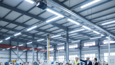
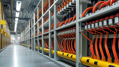
Its main application is moving substantial power between transformers, switchgear, generators, and large motors. Industrial plants use it across production buildings, where long cable runs may create installation challenges. Power stations, substations, data centers, commercial complexes, and renewable energy facilities also use it. A bus duct can reduce floor congestion and provide a cleaner route through crowded electrical rooms.
Choosing the best design requires more than checking voltage and current. Confirm continuous load, short-circuit withstand, insulation level, enclosure protection, ambient temperature, altitude, and installation orientation. The joint system deserves careful attention. Poorly prepared joints can create heat, tracking, or difficult maintenance work. Verify applicable IEC, IEEE, or national requirements with a qualified electrical engineer.
Think about the working environment. Dust, moisture, vibration, and limited access may change the enclosure and maintenance requirements. Ventilated designs can manage heat, but they may need cleaner surroundings. Sealed designs offer stronger protection, yet inspection can become less convenient. No selection method is perfect. Early drawings often miss future load growth, so a practical spare-capacity allowance can prevent expensive replacement later.

Medium voltage bus duct is an enclosed power-distribution system that uses insulated busbars to transmit electricity, typically above 1 kV and up to 35 kV. It is used where compact, high-capacity, and protected connections are required between transformers, switchgear, generators, motors, substations, and large facilities.
The chart shows commonly used nominal system-voltage examples. Actual bus duct ratings must be selected according to the system voltage, continuous current, short-circuit withstand level, insulation coordination, enclosure requirements, installation environment, and applicable standards.
Use MV bus duct for large motors, process equipment, transformers, and plant-wide distribution.
Compact enclosed busbars can connect utility incomers, transformers, generators, and critical distribution equipment.
Higher-voltage bus duct arrangements are used for substation interconnections and generator or transformer links.
How to Choose the Best Medium Voltage Bus Duct?
Start with the system voltage, not the catalogue name. IEC 62271-200 covers metal-enclosed equipment above 1 kV and up to 52 kV. Select the next suitable voltage class, then verify insulation level, power-frequency withstand, and lightning impulse withstand. The IEA’s Electricity 2024 report projects global electricity demand to grow by an average 3.4% annually through 2026. Load growth matters. A bus duct sized only for today may become an expensive restriction.
Calculate continuous current from real demand, motor starting, transformer loading, and future expansion. Then check conductor temperature, enclosure heat dissipation, ambient temperature, altitude, and installation grouping. A 1,600-ampere rating can be misleading when poor ventilation reduces its usable capacity. Field engineers often see this overlooked. It is not a small detail.
Fault level requires a short-circuit study at the installation point. Compare the calculated symmetrical current with the bus duct’s short-time and peak withstand ratings, commonly specified for one or three seconds. IEEE C37.23 provides guidance for metal-enclosed bus applications, while IEEE 1584-2018 supports arc-flash assessment. Do not copy a nearby project’s rating. Cable entry, indoor or outdoor exposure, IP protection, seismic conditions, expansion joints, and maintenance clearance also affect selection. I would question any design that treats installation space as an afterthought. A physically compact duct can still fail the real project requirements.
| Selection Dimension | Typical Design Range or Requirement | What to Verify | Recommended Selection Approach |
|---|---|---|---|
| Rated system voltage | Common medium-voltage applications include 3.3 kV, 6.6 kV, 11 kV, 13.8 kV, 22 kV, and 33 kV. | Nominal line-to-line voltage, highest system voltage, insulation coordination, and system grounding method. | Select a bus duct with a rated voltage equal to or higher than the system’s highest operating voltage, not only its nominal voltage. |
| Rated continuous current | Typical project ratings may range from approximately 400 A to 5,000 A or more, depending on the application and enclosure design. | Maximum load current, future expansion, duty cycle, ambient temperature, altitude, enclosure heat dissipation, and permissible temperature rise. | Calculate the maximum operating current and choose the next suitable standard rating. Avoid sizing only from present average load. |
| Load-current calculation | For a three-phase load: I = P ÷ (√3 × V × power factor × efficiency). | Transformer rating, motor starting current, power factor, efficiency, diversity, and non-linear loads. | Use the worst credible operating condition and include an engineering margin without exceeding the thermal design limits. |
| Short-time withstand current | Common short-time withstand ratings include 16 kA, 25 kA, 31.5 kA, 40 kA, and 50 kA for a specified duration such as 1 second or 3 seconds. | Prospective three-phase short-circuit current at the installation point and the required withstand duration. | The bus duct short-time withstand rating must be equal to or higher than the calculated fault current for the specified time. |
| Peak withstand current | Typical peak withstand values are approximately 2.0 to 2.5 times the short-time RMS withstand current, subject to the applicable standard and system conditions. | Asymmetrical fault current, X/R ratio, system source impedance, and protective-device clearing time. | Check both RMS short-time withstand and peak withstand ratings; one cannot replace the other. |
| Conductor and enclosure construction | Common conductor materials are copper or aluminium. Enclosures may be air-insulated, segregated, or designed with additional internal barriers. | Conductor cross-section, joint design, insulation system, ingress protection, earthing continuity, and accessibility of joints. | Select the construction according to fault level, environmental conditions, maintenance strategy, and required protection against contact or contamination. |
| Installation environment | Indoor, outdoor, dusty, humid, corrosive, high-temperature, high-altitude, or chemically exposed locations may require different designs. | Ambient temperature, humidity, pollution level, solar radiation, water exposure, corrosive agents, seismic conditions, and altitude. | Specify the required enclosure protection and derating factors. Confirm whether standard ratings apply at the actual site conditions. |
| Ingress protection | Indoor clean areas may use a lower protection level than outdoor or wash-down areas, where protection against dust and water is more demanding. | Required IP code, cable-entry points, joint covers, drainage, condensation control, and exposure to water jets or dust. | Choose the IP rating based on the complete installed assembly, including joints, flanges, tap-off points, and transitions. |
| Route and mechanical support | Routes may be horizontal, vertical, rooftop, shaft-mounted, or exposed to vibration and seismic movement. | Route length, bends, expansion joints, support spacing, building movement, vibration, access for assembly, and lifting limitations. | Coordinate the bus duct layout with structural, architectural, fire-protection, and cable-routing drawings before fabrication. |
| Fire and building penetrations | Penetrations through fire-rated walls or floors may require tested fire-stopping systems compatible with the bus duct enclosure. | Fire-resistance rating, penetration dimensions, smoke control, thermal movement, and local building-code requirements. | Use a documented, tested penetration detail; do not rely on generic sealant or unverified site modifications. |
| Voltage drop and power quality | Voltage drop depends on route length, current, conductor impedance, power factor, frequency, and joint resistance. | Continuous voltage drop, motor-starting voltage dip, harmonic currents, and phase-load balance. | Verify impedance and voltage-drop data for the complete route, especially for long runs and large motor or transformer loads. |
| Protection coordination | Protection settings must limit thermal and mechanical fault stress while maintaining the required selectivity and clearing time. | Upstream and downstream breaker ratings, relay settings, current-transformer data, arc-flash study, and discrimination requirements. | Complete a short-circuit and protection-coordination study before confirming the final bus duct rating. |
| Standards and testing | Medium-voltage busbar trunking assemblies are commonly evaluated under IEC 61439-6; associated medium-voltage switchgear may fall under IEC 62271-200. | Applicable national standards, design verification, routine tests, dielectric tests, temperature-rise tests, and short-circuit test evidence. | Require documented compliance with the project standard and test conditions applicable to the complete assembly. |
| Maintenance and commissioning | Inspection intervals depend on environment, operating duty, contamination, thermal loading, and manufacturer instructions. | Joint torque verification, insulation resistance, phase identification, continuity of protective conductors, cleaning, and thermographic inspection. | Select a design that provides safe access to joints and establish commissioning and preventive-maintenance procedures before energization. |
Note: The ratings and ranges shown are general engineering reference values. Final bus duct selection must be confirmed through a site-specific load-flow, short-circuit, protection-coordination, thermal, mechanical, and installation review.
Medium voltage bus duct selection starts with the system layout. Non-segregated designs can reduce cost and space. Segregated or isolated-phase designs provide stronger phase separation and fault control. Compare copper and aluminum conductors by ampacity, weight, voltage drop, and joint performance. Copper handles compact layouts well, while aluminum can reduce weight and material cost. A larger conductor is not automatically better. Short-circuit withstand and heat rise data matter more than appearance.
Insulation needs careful attention. Air-insulated systems may simplify inspection, but they need suitable clearances and clean surroundings. Solid insulation can improve compactness and reduce contamination risks. However, damaged insulation may be harder to detect. Review partial-discharge results, dielectric test records, and service temperature limits. The enclosure should match the installation environment. Outdoor routes need weather protection, drainage, corrosion resistance, and appropriate ingress protection. Indoor systems still require grounding continuity and safe access around joints.
Tips: Request certified type-test reports for temperature rise, short-circuit strength, and dielectric performance. Check every joint location before approval. Field inspections often find alignment problems that drawings miss. Leave room for maintenance, not just installation. I have seen compact designs become difficult to repair later. Confirm conductor sizing with actual load profiles, ambient temperature, altitude, and future expansion. Independent engineering review is valuable when routes are long or fault levels are high.
How to Choose the Best Medium Voltage Bus Duct?
Choosing a medium voltage bus duct begins with site conditions, not a product brochure. In field evaluations, I examine voltage ratings, short-circuit withstand, insulation levels, and temperature-rise data. Verify routine test records and installation procedures. A clean enclosure matters. Check interlocks, shutters, grounding continuity, and access points before energization. These details reduce arc-flash exposure and discourage unsafe maintenance habits.
Environmental protection requires more than an impressive enclosure rating. Match ingress protection to dust, moisture, salt, chemicals, and temperature changes at the site. For outdoor routes, inspect seals, drainage paths, UV-resistant finishes, and expansion joints. In humid rooms, condensation heaters and ventilation space may protect insulation. Do not ignore heat. Poorly planned bends or blocked airflow can create hot spots at joints. A site survey often reveals problems hidden in drawings.
Compliance should be documented, not assumed. Request design calculations, test reports, material certificates, and clear installation instructions. Confirm alignment with applicable IEC, IEEE, and local requirements. The exact rules depend on voltage, location, and the responsible authority. Independent engineering review adds useful distance from sales claims. I have seen teams approve equipment after checking only one certificate. That shortcut is risky. No checklist catches everything. Certificates may not cover field workmanship, torque values, or final clearances. Record torque readings and photograph every joint before covers close.
Choosing the best medium voltage bus duct requires more than comparing purchase prices. A reliable manufacturer should demonstrate controlled engineering, documented testing, and practical installation experience. Start with the manufacturer’s technical history, production capacity, and quality procedures. Ask for design calculations, short-circuit test reports, temperature-rise results, and inspection records. Factory acceptance testing should be clearly defined before the contract is signed. That matters.
Select equipment that suits the complete operating environment, not only the rated voltage. Review conductor material, enclosure protection, joint design, thermal expansion, grounding, and access for maintenance. A low initial quote can hide higher installation costs, energy losses, or difficult spare-part requirements. In project reviews, I have seen small design omissions cause long shutdowns. The cheapest option was not always the least expensive. Sometimes, our own specifications were incomplete.
Tips: Compare total lifecycle value over the expected service period. Include transport, installation, testing, routine inspections, replacement joints, outage risks, and technical support. Request a clear warranty with response times and defined responsibilities. Verify that local technicians can provide assistance, and confirm spare parts will remain available. Ask for references from facilities with similar load levels and environmental conditions. Good evidence beats confident promises.