Leave Your Message

How to Choose the Right Bus Duct for Electrical Systems

Choosing the right Bus Duct In Electrical systems begins with the actual load, not a catalogue rating. A bus duct must carry today’s current, tolerate expected fault levels, and fit the building’s route. Picture a crowded plant room: a narrow ceiling void, hot equipment, and several bends can shape the choice as much as the ampere rating. Small details matter.

The U.S. Department of Energy-supported Lawrence Berkeley National Laboratory report, led by researcher Arman Shehabi and colleagues, estimates that U.S. data centers used about 176 terawatt-hours of electricity in 2023. It projects demand could rise to 325–580 terawatt-hours by 2028. Those figures are not bus-duct sizing instructions. They do show why designers should test future-load assumptions instead of treating them as certainties. Growth forecasts can be wrong.

“Select the busway for verified load, fault duty, environment, and maintainability—not a single headline rating.” That is a practical design principle, not a direct quotation from Shehabi. In this guide, we’ll compare feeder and plug-in busway, copper and aluminum conductors, enclosure ratings, and installation constraints. We’ll also examine voltage drop, expansion plans, and access for inspection. A qualified electrical engineer should confirm calculations against applicable standards and site conditions. The best choice is rarely the largest one; it is the system whose ratings, layout, and future capacity can be documented and checked.

How to Choose the Right Bus Duct for Electrical Systems

Understanding Bus Duct Systems and Their Main Components

How to Choose the Right Bus Duct for Electrical Systems

Understanding Bus Duct Systems and Their Main Components

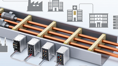
A bus duct, also called a busway, carries electrical power through a protective enclosure. Inside, conductive busbars transfer current between equipment. Insulation and supports keep conductors separated and help maintain their position. The enclosure provides mechanical protection, but its rating must suit the installation environment. Dust, moisture, heat, and corrosive air can all affect the choice. Small details matter.

Sections connect through joints, which need correct alignment and tightening to limit resistance and overheating. End-feed units connect the run to a power source, while tap-off units provide connection points for loads. Elbows and tees help route the duct around beams or equipment. Hangers support overhead sections; bonding paths help maintain electrical continuity.

A common planning miss is leaving too little clearance to inspect joints or remove a tap-off unit. Drawings may look tidy, yet the real route can be crowded.

Check current and voltage ratings, fault withstand, temperature limits, and installation instructions against the system design. Confirm that protection, access, and environmental requirements fit the actual site, not just the specification sheet.

Assessing Electrical Loads and Distribution Requirements

Before choosing bus duct, map the loads it must serve. Record connected equipment, measured peak demand, operating schedules, and planned additions. A nameplate total alone can exaggerate demand; diversity can also hide simultaneous starts or seasonal peaks. Check motor inrush, nonlinear loads, and expected harmonics with qualified electrical professionals. Small details matter. A poorly placed tap-off can leave a long cable run to a machine, complicating maintenance and voltage-drop control.

Growth forecasts matter, but they are not a sizing calculation. Lawrence Berkeley National Laboratory’s 2024 United States Data Center Energy Usage Report estimates that U.S. data centers used about 176 terawatt-hours in 2023, with consumption potentially reaching 325–580 terawatt-hours by 2028. That range signals uncertainty as well as growth. Apply the same caution at facility level: compare utility records, operating plans, and credible expansion schedules rather than treating optimistic projections as guaranteed load. Then verify bus duct ratings against continuous current, ambient temperature, fault current, voltage drop, and installation conditions. Check whether future branches can be added without blocking access or disrupting nearby equipment. I would not pretend every forecast is precise; revisit assumptions when real operating data arrives.

Comparing Bus Duct Types, Ratings, and Materials

Bus duct selection starts with the installation, not the catalogue. Feeder bus duct suits long, fixed runs between transformers and distribution panels. Plug-in systems add tap-off openings for equipment along the route, useful in workshops where loads may shift. Compare continuous current ratings with measured demand and expected expansion. Also check voltage, short-circuit withstand, enclosure rating, and temperature-rise limits. IEC 61439-6 covers busbar trunking systems; its verification framework makes test evidence worth reviewing, not just a nameplate.

Material changes the trade-offs. The Copper Development Association lists copper density at about 8.96 g/cm³, while aluminum is about 2.70 g/cm³, according to Aluminum Association material data. Aluminum is much lighter. Copper offers higher conductivity by mass and can allow a more compact conductor, though actual dimensions depend on design and operating temperature. Aluminum conductors often need greater cross-sectional area for comparable performance. Check joint design and installation instructions closely. Small details matter.

Insulation and enclosure type matter too. Sandwich construction can reduce space needs, while air-insulated designs may ease access for inspection. Neither is automatically better. Compare manufacturer test reports for short-circuit performance, temperature rise, and environmental protection under conditions close to your site. A rating is not a promise under every installation. That distinction is easy to miss. Dust, moisture, ambient heat, and crowded cable rooms can change the practical choice. I would also leave room for uncertainty: future load estimates are often imperfect, so document assumptions before fixing the rating.

Evaluating Installation Conditions and Future Expansion

Installation conditions shape bus duct selection long before the first section arrives on site. Measure ceiling height, corridor width, turning points, and access around equipment. A route that looks clear on a drawing may conflict with sprinkler pipes or lighting trays. Leave room for joint assembly and inspection. Tight spaces need careful planning.

Check ambient temperature, moisture, dust, and possible chemical exposure. These conditions can affect enclosure choice, insulation, and maintenance intervals. Confirm support spacing and structural capacity with qualified electrical and structural professionals. Also review the system’s voltage, current, and short-circuit requirements against project calculations. Small details matter. A nearby heat source, for example, may reduce usable capacity.

Future expansion deserves equal attention. Estimate likely load growth, then decide whether spare capacity, extra tap-off points, or an accessible extension path makes sense. Avoid oversizing without evidence; unused capacity can add cost and occupy valuable space. Yet a route with no room for another section can make later work disruptive. It is easy to over-plan. Still, a modest allowance for spare space and accessible joints may prevent a difficult retrofit. Record the assumptions behind growth estimates, and revisit them when equipment layouts change.

How to Choose the Right Bus Duct for Electrical Systems - Evaluating Installation Conditions and Future Expansion

Selection Dimension What to Evaluate Practical Selection Guidance Design or Installation Check
Load current and capacity Calculated demand current, load diversity, motor starting, harmonics, and anticipated changes to the load. Select a rated current that meets the calculated demand after applicable correction factors. Avoid choosing solely from connected load or nominal equipment ratings. Confirm the design current, protective-device rating, conductor temperature limits, and any required derating with the project engineer and applicable electrical code.
Voltage and system configuration Nominal system voltage, frequency, number of phases, neutral requirements, and earthing arrangement. Match the bus duct’s voltage rating and conductor configuration to the supply system. Specify a full-size neutral where required by the load profile or local rules. Check phase sequence, neutral loading, protective-earth continuity, and compatibility with connected equipment before installation.
Conductor material Electrical performance, installation weight, joint design, available space, and lifecycle cost. Copper and aluminum systems can both be suitable. Compare the complete system’s current rating, dimensions, weight, connection method, and total installed cost rather than material alone. Use the specified joint hardware and installation procedure. Do not mix conductor systems or joint components unless the system is designed and approved for that combination.
Installation route and mounting Horizontal or vertical runs, ceiling clearance, support spacing, structural capacity, access, and route changes. Choose straight lengths, elbows, tees, offsets, and tap-off locations to suit the actual route. Provide supports in accordance with the system instructions and project design. Coordinate the route with building services and structural elements. Allow access for joint assembly, inspection, and future maintenance.
Ambient and site conditions Maximum ambient temperature, ventilation, altitude, moisture, dust, corrosive agents, and indoor or outdoor exposure. Use a system rated for the site environment. Elevated temperature, restricted ventilation, or other specified conditions may require derating or a different enclosure. Confirm the manufacturer’s rating conditions and any correction factors. Protect exposed equipment from condensation, corrosion, and physical damage as required.
Ingress protection Expected exposure to dust, water, cleaning, and the location of the run or tap-off units. Select an IP rating appropriate to the exposure. For example, IP54 is dust-protected and protected against splashing water; IP55 adds protection against water jets. Check the rating of the complete installed assembly, including joints, end covers, tap-off units, and penetrations—not just the straight sections.
Short-circuit withstand Prospective fault current at the installation point and the protective device’s operating characteristics. The bus duct’s short-time and peak withstand ratings must be suitable for the fault level and the clearing performance of the upstream protection. Verify coordination using the system’s declared ratings and the project fault study. Do not assume that a higher continuous-current rating guarantees adequate fault withstand.
Protection and tap-off points Load distribution, branch-circuit ratings, isolation needs, and the number and locations of future outlets. Plan tap-off units around the equipment layout and expected branch loads. Each outgoing circuit requires appropriately rated protection and a suitable means of isolation where required. Confirm tap-off compatibility, interlocking or isolation provisions, accessibility, and compliance with local installation requirements.
Fire barriers and building penetrations Wall and floor penetrations, fire-compartment boundaries, and the building’s fire-resistance requirements. Use suitable tested fire-stopping arrangements at penetrations and any fire-barrier components required by the system design and building code. Coordinate fire-stopping details with the building design. Ensure penetrations preserve the required fire performance and do not obstruct inspection or maintenance.
Thermal movement and expansion Run length, temperature variation, building movement, and changes in direction or support conditions. Provide expansion provisions where required by the system design, installation instructions, and expected movement of the run. Follow the specified locations and installation details for expansion units, sliding supports, and fixed points; do not treat ordinary joints as expansion joints.
Future expansion and spare capacity Planned equipment additions, likely load growth, spare tap-off positions, and available route space. Allow practical capacity and physical space for planned growth. Consider reserved tap-off locations and accessible connection points without oversizing the system without justification. Check that future additions will remain within current, fault, voltage-drop, and protective-device limits. Confirm that modifications can be made safely and in accordance with the system instructions.
Voltage drop and energy performance Run length, current, conductor material, operating temperature, and the sensitivity of connected loads. Evaluate voltage drop across the complete feeder and compare it with the project design limits and applicable requirements. Use system-specific electrical data and the actual route length. Include joints and operating conditions where required by the calculation method.
Standards and documentation Applicable jurisdiction, product standard, inspection requirements, and required technical records. Specify a busbar trunking system suitable for the relevant installation rules; IEC 61439-6 is a commonly used standard for busbar trunking systems where adopted. Review ratings, installation instructions, drawings, test documentation, and maintenance guidance before procurement and commissioning.

Note: Final selection depends on the project’s load calculations, fault study, site conditions, local electrical regulations, and the declared ratings and installation instructions for the selected system.

Checking Safety Standards and Compatibility with Equipment

Before selecting a bus duct, check which electrical codes and product standards apply to the project. Requirements vary by location and installation type. Confirm that the equipment carries suitable certification and that its voltage and current ratings match the system. A rating that looks adequate on paper may not account for continuous loading or the available fault current.

Compatibility goes beyond the main ratings. Compare the bus duct’s short-circuit withstand rating with the protective device and system fault level. Check the phase, neutral, and grounding arrangement, plus the connection details at switchgear, transformers, and panels. Enclosure type matters too: a dusty plant room, damp service area, or outdoor route may need different environmental protection. Small details matter. Measure clearances and verify support locations against the actual equipment, not only an old drawing.

A common oversight is assuming that matching voltage and current ratings guarantees a suitable fit. It does not. Confirm joint orientation, access for installation, and room for thermal expansion along long runs. Manufacturer documentation and project specifications should support these checks. When ratings or interfaces are unclear, ask a qualified electrical engineer to review them before procurement. Field conditions can differ from plans, and that difference deserves attention.