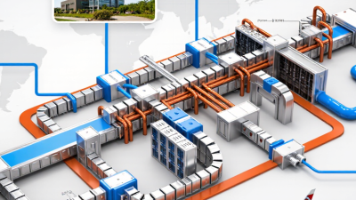
Busway Electrical systems carry power through compact, enclosed conductors, but choosing one is not a catalog exercise. A buyer must match the system to load, route, installation space, and future maintenance. “Fit the busway to the real operating conditions, not just the headline rating.” — [Insert a verified quotation from a named busway electrical expert.] This quotation should be confirmed with its source before publication; no expert statement was supplied for this draft.
This guide examines major busway types for global buyers in 2026, including feeder and plug-in systems, as well as designs suited to different installation environments. A factory line may need frequent tap-off points. A data center may prioritize predictable distribution and clear maintenance access. Details matter. A short route through a crowded ceiling can expose problems that a product brochure never shows.
The comparison also considers conductor material, current rating, enclosure protection, installation flexibility, and lifecycle needs. These factors help buyers build a more useful shortlist before requesting quotations or reviewing project specifications. Still, no single type suits every facility. Regional product availability and project requirements vary, so buyers should verify technical claims with manufacturers and qualified electrical professionals. That extra review can feel slow. It may also prevent an expensive mismatch.
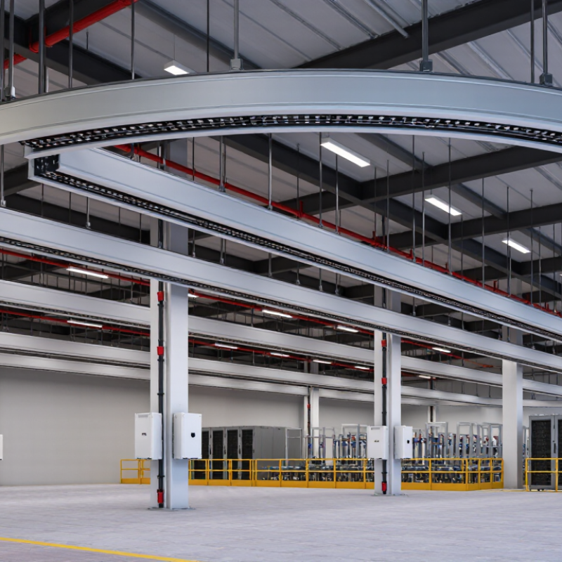
Busway systems distribute electrical power through enclosed conductors, creating a structured route between a supply point and connected equipment. Unlike long runs of separate cables, busway sections connect through joints and fittings. This can make power routes easier to adapt when a facility’s layout changes.
Inside the enclosure, copper or aluminum conductors carry current. Insulating supports keep them separated, while the metal housing provides mechanical protection and may serve as a grounding path when designed for that purpose. Joint connections need careful alignment and tightening. A poorly seated joint can create a hot spot, so installers should follow the specified torque values and verify connections during commissioning.
Small details matter. The system’s rating must suit the expected load, ambient temperature, and installation conditions. Plug-in units allow power to be tapped along compatible sections, but their placement and protection still require engineering review. Clearances, support spacing, and access for inspection are easy to underestimate. No layout is perfect; future loads may differ from today’s plan. Routine thermal checks can reveal developing problems, though they cannot replace correct installation or load calculations.

Busway systems differ most visibly in how their conductors sit inside the enclosure. In a sandwich design, copper or aluminum bars are tightly layered with solid insulation between them. This creates a compact profile that can suit narrow electrical rooms and dense service corridors. The shorter spacing can also affect heat dissipation, so engineers should check rated current and installation conditions together.
Air-insulated busway keeps more space between conductors, using the surrounding air and insulating supports to maintain separation. Its larger housing may be easier to inspect, but it needs more room. A quick site measurement can prevent a costly fit problem. Conductor layout matters too: flat, edgewise, or phased arrangements change the busway’s width, heat distribution, and connection points. Four-wire systems add a neutral conductor, often important where loads are unbalanced.
The right choice depends on more than a catalog rating. Check ambient temperature, available clearance, fault levels, and how frequently tap-off points may be needed. Solid insulation can offer a compact assembly, while air insulation may provide clearer visual access to components. Neither is automatically better. Installation quality matters. Small gaps, poorly aligned joints, or overlooked support spacing can undermine an otherwise suitable design. I would verify the manufacturer’s tested configuration against the actual site drawings, because a busway that looks right on paper may still clash with a beam or cable tray.
| Busway Type | Conductor Layout | Insulation and Construction | Typical Applications | Selection Considerations |
|---|---|---|---|---|
| Compact sandwich busway | Flat phase conductors are arranged closely together, commonly with neutral and protective-earth conductors in the same assembly. | Conductors are insulated and packed closely within a metal enclosure; the compact construction reduces the space needed for the run. | Commercial buildings, industrial facilities, and data-center power distribution. | Check the required current rating, temperature limits, short-circuit withstand, enclosure rating, and installation clearances. |
| Air-insulated busway | Conductors have greater spacing within the enclosure than in a compact sandwich design; phase arrangement depends on the manufacturer’s design. | Electrical clearance is provided mainly by air, with insulating supports or barriers used to position and separate conductors. | Industrial distribution routes and installations where a larger busway profile is acceptable. | Allow for enclosure dimensions, ventilation and environmental conditions, support spacing, and the specified protection level. |
| Non-segregated-phase bus duct | Multiple phase conductors share a common enclosure without grounded metal barriers separating each phase. | Phase separation relies on air clearances, conductor insulation, and the support system specified for the assembly. | Power distribution between electrical equipment in industrial and utility installations. | Confirm the assembly’s fault withstand, insulation system, environmental suitability, and project-specific installation requirements. |
| Segregated-phase bus duct | Phase conductors share a common enclosure but are separated from one another by barriers. | Nonconductive barriers divide the phases; the phases are not each enclosed in their own grounded metal housing. | Industrial and power-generation connections where phase barriers are part of the required design. | Review barrier construction, system voltage, short-circuit rating, and access or maintenance requirements. |
| Isolated-phase bus duct | Each phase conductor is enclosed in its own separate housing, typically with the enclosures electrically bonded and grounded. | Grounded metal enclosures isolate the phases; the design is generally engineered for high-current power connections. | Generator-to-transformer connections and other large-scale power-generation installations. | Consider project-specific current and fault levels, enclosure routing, thermal performance, supports, and expansion provisions. |
| Three-phase conductor configurations | 3P3W: three phases; 3P4W: three phases plus neutral; 3P5W: three phases, neutral, and a separate protective-earth conductor. | These describe the number and function of conductors, not a specific insulation style. They can be offered in different busway constructions. | Selection depends on the connected loads, neutral-current requirements, and the facility’s earthing arrangement. | Specify the conductor configuration separately from the busway construction and confirm compatibility with local electrical requirements. |
Note: Busway construction, ratings, and available configurations vary by design. Verify the applicable project specifications and standards, such as IEC 61439-6 or UL 857 where relevant.
Busway systems are commonly classified by construction and by the job they perform. Air-insulated busway uses space around conductors, while compact sandwich designs place insulated conductors close together. The compact form can help in crowded electrical rooms, but installation clearances and heat dissipation still need careful review. Small details matter.
Feeder busway carries power between major equipment, such as a transformer and a distribution panel. Plug-in busway adds tap-off points along the route, allowing loads to connect at planned locations. Lighting busway serves lower-load circuits across workshops or retail spaces. These categories overlap in real projects, so the product label alone does not confirm suitability.
Selection starts with the load profile, route length, and expected future expansion. Engineers should check rated current, short-circuit withstand capability, voltage drop, enclosure protection, and ambient temperature. A long run above hot machinery may behave differently from the same rating in a cool corridor. Tap-off units also need spacing that matches equipment layouts and maintenance access. One point is easy to overlook: a flexible layout may invite later changes, yet every modification should be checked against the busway’s ratings and installation instructions. Category names are useful, but project conditions decide the fit.
2026 Top Busway Electrical Types for Global Buyers
Matching Busway Types to Loads, Buildings, and Environments
Busway selection starts with the load profile, not a catalog label. Feeder busway suits main distribution between transformers, switchboards, and large equipment. Plug-in busway supports branch circuits where machinery or work areas may change. Check current rating, voltage, fault withstand, and future capacity against the actual project data. Extra capacity can help, but oversizing every run may add cost and installation weight.
Building layout matters just as much. Sandwich busway offers a compact, enclosed route for many indoor installations. Air-insulated designs may suit projects where clearances and maintenance access are manageable. In tight ceilings, measure bends, joints, and service space before choosing a route. Dust matters. For damp, hot, or corrosive areas, confirm the enclosure rating and material suitability with qualified project engineers. A clean drawing can still miss a difficult site condition; that deserves a second look.
Tips: Match plug-in outlet spacing to equipment locations. Verify support spacing, thermal limits, and fault ratings from project documents. Keep access clear. If loads may shift, plan spare outlets and expansion space, but avoid assuming every future need is known.
Matching busway types to loads, buildings, and environments
Indicative application fit is scored from 1 (limited fit) to 5 (strong fit), based on typical busway characteristics. Ratings are qualitative, not a standardized performance measure; confirm current capacity, enclosure rating, installation conditions, and local code requirements for each project.
Global buyers should compare busways by application, not headline amperage alone. IEC 61439-6 covers low-voltage busbar trunking systems, including design and verification requirements. Check the rated current, short-circuit withstand, enclosure protection, and ambient-temperature limits against the project specification. A 2024 IEA report projected global electricity demand growth averaging 3.4% annually from 2024 to 2026. That trend makes capacity planning important, but it does not replace a site-specific load study.
Installation details can change the right choice. Measure the route, ceiling height, and equipment clearances before selecting straight lengths or fittings. Confirm tap-off positions match the actual machinery layout; a small shift can create awkward cable runs. Review local electrical rules and required approvals with a qualified engineer, since IEC alignment alone may not satisfy every market. One detail is easy to miss: ambient heat near boilers or rooftop equipment can affect allowable current.
Tips: Compare ratings under the same temperature and installation conditions. Ask for test documentation, short-circuit data, and jointing instructions. Leave room for future connections, but avoid paying for capacity without a credible load forecast. A tidy drawing helps; it is not the installation.